Claude Loullingen
Let no grass grow under your feet. You are what you create.
Let no grass grow under your feet. You are what you create.
Wiring, pin layout and signals on the door of a Jeep Wrangler JK Moab 2013

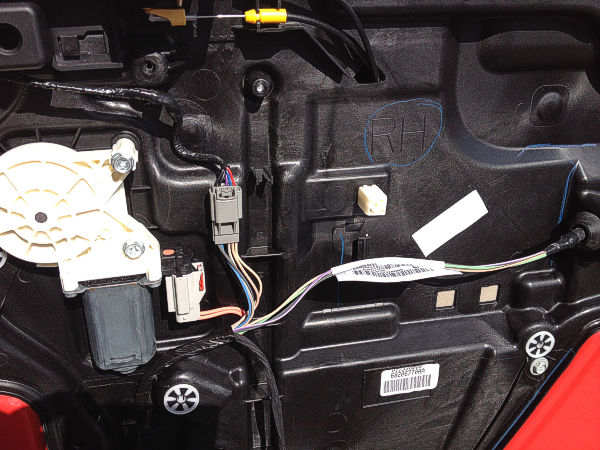
Removing the door panel:
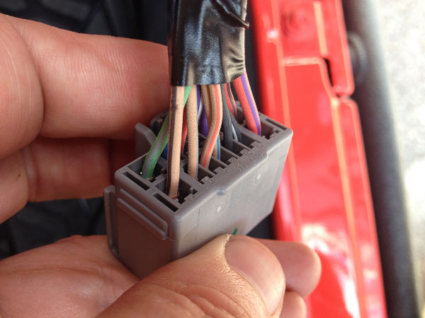
You will find a description here how to remove the door panel. After that you should see this.

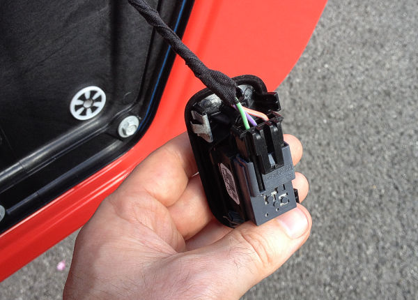
Wiring:
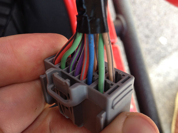
Signals & pin layout:
All the signals have been measured when the door was connected.
Pin |
lead color driver side |
lead color passenger side |
component |
signal |
1 |
brown / yellow |
green / grey |
locking actuator |
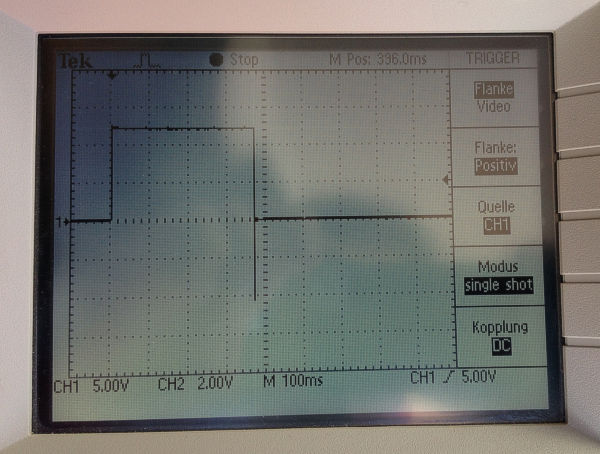
12V during 380ms when locking the door.
Connected to ground when unlocking the door. (When locking with the locking button on the door, the door needs to be closed. See also pin 4.) |
2 |
dark blue / light blue |
blue / light blue |
mirror |
12V when the rear window heater is switched on. |
3 |
red / grey |
red / grey |
button central locking |
13Ω towards ground. |
4 |
violet |
violet / white |
locking actuator |
Connected to ground when the door is open. Without connection when the door is closed. |
5 |
violet / green |
violet / green |
central locking button |
5V when button is pushed. 2,5V when the button to lock the door is pushed. 1,2V when the button to unlock the door is pushed. |
6 |
green / brown |
green / brown |
central locking button |
1Ω towards ground. |
7 |
red / green |
red / dark green |
window lifter |
12V when the window is lifted. Ground when the window is lowered. |
8 |
brown / white |
brown / black |
locking actuator |
12V during 380ms when unlocking the door. Connected to ground when locking the door. |
9 |
brown / green |
brown / grey |
mirror |
12V when the mirror is pushed up. |
10 |
brown / red |
brown / red |
mirror |
12V when the mirror is pushed to the left. |
11 |
brown / blue |
brown / blue |
mirror |
12V when the mirror is pushed down or to the right. |
12 |
black |
black |
locking actuator |
ground |
13 |
black / white |
black / white |
mirror |
ground |
14 |
red / white |
red / blue |
window lifter |
12V when the window is lowered. Ground when the windows is lifted. |
Disclaimer:
I do not take over any warranty or responsability for any damage that might occur through the information published here.